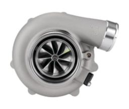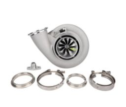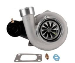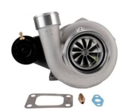
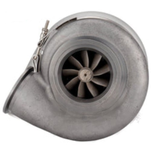
A new turbocharger arrives, the oil and water fittings are sorted, and the compressor outlet is pointing where it needs to go. Then you notice there is no nipple for the boost compensator or wastegate reference hose.
An undrilled compressor housing is common on universal aftermarket turbos and does not, by itself, mean a part is missing. Depending on the housing and the installation, you can use an existing factory pressure port, drill and tap a suitable location, or take the pressure signal from the charge pipe.
The important decisions are where the signal needs to come from, whether the housing is suitable for machining, and how to keep every trace of swarf out of the turbo and engine.
What is a boost compensator or boost reference line?
The small hose carries a pressure signal; it does not carry the engine's main airflow. On a conventional pneumatic wastegate, that signal acts on the actuator diaphragm to help control boost. A manual boost controller or electronic boost-control solenoid may sit between the pressure source and the actuator.
On a mechanically injected turbo diesel, “boost compensator” usually refers to the injection pump's boost-sensitive fuel-control mechanism. Its hose supplies the pressure signal used to adjust fuel delivery as boost changes. That is a different job from operating a wastegate.
Identify what the hose operates before selecting its pressure source. A wastegate, diesel injection-pump compensator, blow-off valve and fuel-pressure regulator should not automatically share the same connection or plumbing arrangement. For a diesel pump, follow the pump supplier's or diesel tuner's specified reference location.
Why do many turbos arrive without a drilled pressure port?
A universal turbo can be installed on different engines, with different compressor-cover orientations, wastegate positions and boost-control arrangements. An undrilled housing lets the installation use a suitable fitting position or a separate charge-pipe pressure source.
However, this varies by model and housing. It would be misleading to say that every performance turbo needs drilling: Garrett lists a machined pressure port on the G30-770, for example. Other housings may have an undrilled casting boss, an existing nipple, or a threaded port closed with a plug.
Check the exact turbo part number and inspect the cover before buying a tap. A turbo speed-sensor port is not a substitute for a boost-reference port.
Where should the pressure port be located?
Use the manufacturer's designated pressure-port boss where one is provided and confirmed for that purpose. If the cover has no designated boss, have a turbo specialist or machinist assess a suitable section of the pressure-side volute or outlet neck. The volute is the scroll-shaped passage that collects compressed air around the compressor wheel.
A practical location needs:
- Access to compressed air: the hole must open into the pressure-side passage, not the compressor inlet or an anti-surge recirculation passage.
- Enough sound material: the wall or boss must support the chosen thread without cracking or leaving inadequate engagement.
- A clear drilling path: inspect the inside of the removed cover, including the opposite wall, before drilling.
- Fitting clearance: allow room for the fitting, tools and hose after the cover is clocked into its final position.
- Internal clearance: the installed fitting must stay clear of the compressor wheel and must not project unnecessarily into the airflow.
Do not choose a spot simply because it is easy to reach with the turbo assembled. Avoid thin sections, clamp lands, sealing faces, O-ring grooves and the close-clearance surface surrounding the compressor wheel. A raised casting feature is not automatically a pressure-port boss.
There is no universal “drill here” position or minimum wall thickness that suits every cover. If the casting cannot support the required thread, use a charge-pipe port rather than forcing a larger fitting into it.
Compressor pressure and manifold pressure are different signals
Under load, pressure at the compressor outlet can be higher than pressure in the inlet manifold because the intercooler and piping create pressure losses. On a throttled engine, closing the throttle also separates conditions in the charge pipe from those in the manifold.
For many conventional pneumatic wastegate systems, a dedicated pressure source close to the compressor outlet is appropriate. Turbosmart's basic actuator instructions specify a boost-only source close to the compressor and caution against a manifold source for that arrangement. Always follow the instructions for your actual actuator and controller.
A typical pneumatic blow-off valve needs a manifold reference downstream of the throttle so it can respond to throttle closure. A boost-referenced fuel-pressure regulator also normally needs manifold pressure. A diesel pump compensator needs the reference location specified for its calibration.
Moving an existing reference from the compressor to the manifold, or vice versa, can change system behaviour. Have the boost control or diesel fuel calibration checked after changing the source.
Tools and parts to organise first
- The correct pressure fitting, with a hose barb matched to the hose.
- A matching tap and the tap manufacturer's specified drilling size.
- A drill press or suitably controlled machining setup, soft jaws and a tap wrench.
- Cutting lubricant suitable for the housing material.
- Deburring tools, suitable cleaning products and clean inspection equipment.
- Thread sealant appropriate to the fitting, housing material and operating temperature.
- Pressure- and temperature-rated reference hose, clamps and heat protection where required.
- The turbo manufacturer's cover-removal, assembly and tightening instructions.
Do not confuse NPT with BSP
A 1/8-inch NPT fitting is a common option, but it is not a universal turbo specification. NPT, BSPT and BSPP are different thread forms; similar-looking fittings should not be mixed. Straight-thread fittings may need a washer or O-ring sealing arrangement rather than relying on thread sealant.
For a 1/8-27 NPT thread, guidence lists an 8.6 mm tapping drill. Use this as a worked example, not a specification for every fitting: follow the instructions for the tap and thread you actually use. The nominal 1/8-inch pipe size is not the drill diameter.
How to drill and install the pressure fitting
1. Confirm the source and final housing orientation
Identify the hose's destination and check its plumbing instructions. Trial-fit the turbo and clock the cover as required, while maintaining the manufacturer's centre-housing orientation requirements. Check the fitting and hose will clear the engine, actuator, brackets and nearby hot components.
2. Remove the compressor cover
Remove the cover completely before drilling or tapping. Follow the model-specific procedure and record the cover and actuator-bracket positions. Some housings use bolts, clamps or a large retaining ring; do not assume they all separate the same way.
Protect the exposed compressor wheel and centre assembly from tools, dirt and cleaning products. Do not undo the compressor-wheel nut or dismantle the rotating assembly for this job. If cover removal requires unfamiliar tooling or disturbs a calibrated actuator arrangement, have a turbo specialist do the work.
Grease on a drill bit, a rag inside the outlet or a vacuum cleaner cannot reliably keep all chips out of an assembled turbo. They do not replace removing the cover.
3. Inspect and mark the location
Inspect both sides of the chosen area. Confirm wall thickness, thread engagement, tool access and the final fitting's internal clearance. Secure the cover without distorting it or damaging its machined surfaces. Mark the hole centre and use a suitable spotting method to stop the drill wandering on a curved casting.
4. Drill the tapping hole
Align the drill with the intended thread axis. Use the specified tapping-drill diameter, appropriate cutting speed and lubricant, and controlled feed. Plan the drill travel so breakthrough cannot damage the opposite wall or another part of the housing. Clear chips as you work and lightly deburr the hole without removing material needed for thread engagement.
5. Tap the thread progressively
Start the matching tap square to the hole. Use suitable lubricant and the cutting technique recommended for the tap, clearing chips regularly.
A tapered pipe thread becomes larger as the tap goes deeper. Cut progressively and check engagement with an appropriate thread gauge or fitting check as specified by the tooling and fitting supplier. Do not run the tap in to an arbitrary depth or force a fitting in to compensate for a poorly cut thread. An over-deep taper thread can leave the fitting loose; an undersized or shallow thread can encourage overtightening and crack the casting.
6. Deburr, clean and inspect
Remove burrs from both sides of the hole. Thoroughly clean the detached cover, including the volute, outlet, threaded hole and any recirculation passages. Remove cutting lubricant and all metal chips, then dry and inspect under good light. Use cleaning products compatible with the housing and seals.
Do not blow swarf towards the exposed centre assembly or spin the turbo with compressed air. If any debris has reached the compressor wheel or centre assembly, stop and have the turbo inspected before use.
7. Install the fitting and refit the cover
Apply the specified sealant sparingly to the appropriate male threads, keeping the leading threads and pressure passage clear. Avoid excess sealant or loose tape that could block the small signal line. Tighten to the fitting supplier's specification; do not keep tightening a tapered elbow simply to make it point in the desired direction.
Check the fitting's inner end is clear of the wheel and airflow path. Refit the cover to the turbo manufacturer's procedure, inspect or replace seals as required, and tighten the retaining hardware correctly. Verify that the compressor wheel turns freely without touching the cover and restore any actuator settings according to the manufacturer's instructions.
8. Connect and secure the hose
Use the hose size and material specified for the connected device. Keep the run practical and direct, allow for engine movement, and avoid kinks, abrasion and exhaust heat. Secure the hose ends with suitable clamps.
Follow the controller's exact port diagram. Do not assume numbered solenoid ports or top and bottom wastegate ports are interchangeable. Keep the wastegate reference dedicated unless the manufacturer explicitly permits sharing; Turbosmart's Boost Tee troubleshooting guidance specifically advises against extra tees in its pressure-source-to-actuator line.
9. Leak-test and verify operation
Use a regulated pressure-test setup and the manufacturer's test procedure. Stay within the lowest pressure rating of every connected component; do not apply unrestricted workshop air. Check the fitting and hose connections for leakage and confirm the line is unobstructed.
Verify actuator and boost-control operation before applying significant engine load. A disconnected or leaking wastegate reference can cause uncontrolled boost. Initial load testing should use a conservative, manufacturer-approved control setup with boost monitored by the tuner. Check overboost protection and review calibration if the reference location has changed. For a diesel compensator, have the diesel tuner check fuel delivery and exhaust temperatures under load.
Alternatives to drilling the compressor housing
| Option | When it makes sense | What to check |
|---|---|---|
| Existing factory pressure port | The cover already has a designated threaded pressure port or nipple. | Confirm its purpose and thread. Keep speed-sensor and other ports separate. |
| Threaded boss in a charge pipe | The cover lacks suitable material, or access is better in the pipe near the compressor outlet. | Use a suitable welded boss or designed adapter. Remove the pipe for fabrication and cleaning; leak-test afterwards. |
| Ported outlet adapter or purpose-built coupler fitting | A compatible component can provide a pressure take-off without machining the cover. | Check pressure and temperature ratings, sealing and retention. Use a designed system rather than pushing a loose barb through silicone. |
| Existing manifold port or vehicle-specific reference adapter | The connected device specifically needs a manifold signal. | Confirm device requirements and calibration. A manifold source is not automatically suitable for a wastegate. |
A charge-pipe boss close to the compressor outlet can be a sensible solution when the housing has no suitable drilling location. It also lets you remove and work on the pipe separately. The best option is the one that gives the device the correct signal with sound mechanical support and reliable sealing.
The detail that matters to the whole turbo system
Turbo selection is only part of a reliable installation. The wastegate, pressure source, reference hose, boost controller and calibration need to work together. A good turbo cannot compensate for a blocked fitting, cracked hose or incorrect control plumbing.
Spool Imports supplies Pulsar turbochargers and accessories. If you are planning an installation, contact Spool with the turbo part number, engine, wastegate and controller details, plus a photo of the housing. Those details help establish the right parts and reference arrangement before machining begins.
Frequently asked questions
Do all turbochargers need the compressor housing drilled for a boost reference?
No. Some turbochargers have a factory pressure port or nipple, while others use an undrilled housing. A suitable charge-pipe pressure port can also avoid drilling the compressor cover.
Can I drill the compressor housing with the turbo assembled?
Remove the compressor cover before drilling or tapping. Grease, rags and vacuum extraction do not reliably prevent metal chips reaching the compressor wheel or engine.
Where should I drill a compressor housing for a boost reference?
Use the manufacturer's designated pressure-port boss where available. Otherwise, a turbo specialist should confirm a suitable pressure-side location with adequate material, thread engagement and internal clearance.
What size drill do I need for a 1/8-inch NPT boost fitting?
Guidence lists an 8.6 mm tapping drill for 1/8-27 NPT. Confirm the drilling size with your actual tap supplier and fitting specification; 1/8-inch is the nominal pipe size, not the hole diameter.
Can a diesel boost compensator use the wastegate pressure line?
Do not assume the lines can be shared. The diesel pump and wastegate may have different reference requirements, and some boost controllers prohibit extra tees in the wastegate line. Follow the pump supplier's, tuner's and controller manufacturer's instructions.